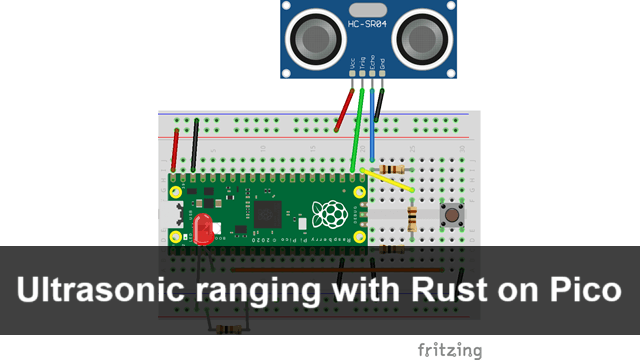
This article describes how to connect the ultrasonic ranging module HC-SR04 to a Raspberry Pi Pico and control them with the Rust language to measure distances to objects.
Specifications
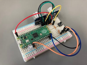
(Note: the orientation and wiring of the ultrasonic distance-measuring module differs between the photograph and the circuit diagram.)
When the tact switch is pressed, the distance to the object in front of the transmitter/receiver of the ultrasonic distance measurement module is measured.
The measured distance is sent to a PC or other device via serial communication.
LED, when connected, the closer the distance, the brighter the LED.
According to the datasheet of the ultrasonic ranging module, the measurable range is 2-450 cm.
What you need
- Raspberry Pi Pico
- Ultrasonic distance-measuring module (HC-SR04)
- Tact switch
- Resistor (suitable quantity)
- Jumper wire(suitable quantity)
- (LED)
Circuit
Circuit diagram
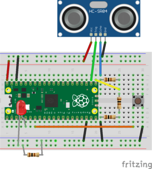
Explanation
HC-SR04 (VCC)
Power supply. Connect to VBUS (5V).
HC-SR04 (Trig)
Input pulses from the Raspberry Pi Pico to initiate ultrasonic transmission.
Connect to GPIO17.
HC-SR04 (Echo)
Outputs a pulse when ultrasonic waves are received.
Connect to ground (GND) on the opposite side of the bullet board via three identical resistors. Here, connect the downstream of the first resistor to GPIO16 as an input to the Raspberry Pi Pico.
The output voltage of the HC-SR04 is 5V, so inputting it directly to the Raspberry Pi Pico, which operates at 3.3V, will cause it to malfunction. Therefore, the input is adjusted to become \(5\times\frac{2}{3}=3.3\ldots V\) using three resistors.
HC-SR04 (GND)
Ground. Connect to GND of Raspberry Pi Pico.
Tact switch
Connect to GPIO5 to control the voltage.
LED
Not required. Change the brightness with PWM according to the measured distance.
Connect the + pole to GPIO3 and the - pole to GND via a resistor.
Source code
GitHub
The source code is available on GitHub. The crates, etc. used can be found in ../Cargo.toml.
Explanation
The detailed techniques for each are described in the following collection of implementation examples.
Tact switch
// Set an input from a switch to gpio5
let switch = pins.gpio5.into_pull_up_input();
Set the control pin of the tact switch to GPIO5. Pull up input, so high when no button is pressed.
// Switch on/off
let mut switch_flg = false;
switch_flg manages the state of the button. The state of the button is false if it is not pressed.
// Switch on
if switch.is_low().ok().unwrap() {
    if switch_flg {
        continue;
    } else {
        // Trigger ultrasonic pulse
        // ...
        switch_flg = true;
        // ...
    }
} else {
    switch_flg = false;
}
If the switch is pressed (low) and switch_flg is true, it is assumed to be "pressed continuously" and no action is taken.
If false, it is assumed to be newly pressed and a pulse for ultrasonic ranging is emitted.
HC-SR04
// Set an input from a ultrasonic ranging sensor (echo) to gpio16
let echo = pins.gpio16.into_pull_down_input();

// Set an output to a ultrasonic ranging sensor (trigger) from gpio17
let mut trigger = pins.gpio17.into_push_pull_output();
Set echo as pull down input to GPIO16 and trigger as push pull output to GPIO17.
// Create a timer
let timer = hal::timer::Timer::new(pac.TIMER, &mut pac.RESETS);
Define a timer for measuring time.
// Trigger ultrasonic pulse
trigger.set_low().ok().unwrap();
delay.delay_us(2);
trigger.set_high().ok().unwrap();
delay.delay_us(10);
trigger.set_low().ok().unwrap();
Following the example of use in the data sheet, a 10 microsecond pulse is emitted from the trigger and ultrasound is emitted from the HC-SR04.
// Measure the time it took for the pulse to come back
let mut time_low = 0;
let mut time_high = 0;
while echo.is_low().ok().unwrap() {
    time_low = timer.get_counter().ticks();
}
while echo.is_high().ok().unwrap() {
    time_high = timer.get_counter().ticks();
}
let time = time_high - time_low;
The state echo=low is maintained until the ultrasound is emitted, during which time time_low is continuously updated, so that this variable represents the "time when ultrasound was emitted".
After that, echo=high is set, and this state is maintained until the receiver catches the reflected wave. In other words, by continuously updating time_high during this period, this variable will eventually contain "time when the reflected wave is received".
By finding the difference between these, the "time (microseconds) between the emission of the ultrasonic wave and its return after being reflected by an object" can be determined (time).
// Convert the time to the distance (cm)
let distance = time as f64 * 0.0343 / 2.0;
The speed of sound is \(343\mathrm{m/s}=3.43\times 10^4\mathrm{cm/s}=0.0343\mathrm{cm/\mu s}\) and the distance can be found by dividing time by this.
However, since this is the distance from HC-SR04 to the object and back, the distance to the object is further divided by 2.
(LED)
// Init PWMs
let mut pwm_slices = hal::pwm::Slices::new(pac.PWM, &mut pac.RESETS);

// Configure PWM1
let pwm = &mut pwm_slices.pwm1;
pwm.enable();
pwm.set_top(24999);
pwm.set_div_int(100);
pwm.set_div_frac(0);

// Output channel B on PWM1 to the LED pin
let channel = &mut pwm.channel_b;
channel.output_to(pins.gpio3);
An LED to express distance in terms of light intensity are set to GPIO3 and controlled as PWM.
For more information on PWM, see Implementation examples.
// Adjust the brightness of the LED according to the distance
if distance > 100.0 {
    channel.set_duty(1000);
} else {
    channel.set_duty((64535 as f64 * ((100.0 - distance) / 100.0)) as u16 + 1000);
}
When the distance is 100 cm or more, the duty ratio (specified as a 16-bit unsigned integer) is set to a minimum value of 1000; when the distance is shorter than this, the duty ratio is set to the range 1000-65535, where the shorter the distance, the stronger the duty ratio.
$$\mathrm{Duty}=(65535-1000)\times\frac{100-\mathrm{distance}}{100}+1000$$
シリアル通信
let mut writer = Writer::new();Use the serial_write crate for displaying strings and numbers via serial communication.
// Display the distance
let _ = writer.write_f64(distance, 2, &mut serial);
let _ = writer.writeln_str("cm", &mut serial);
The measured distance is transmitted via serial communication.
For details, see implementation examples.
Comments