This article is a collection of tips for embedding the Rust language into a Raspberry Pi Pico.
You can find the corresponding code notation by what you want to achieve with each electronic part.
We will add to it from time to time, so it might be a good idea if you come back to look at it often.
Basics of development
What you need.
Obviously, you need a Raspberry Pi Pico.
You should solder the pin headers and stick them into the Bullet Board.
Then there are LEDs and resistors to check the operation at the very least. If necessary, various sensors, motors and jumper wires are good to have.
Building the environment
For instructions on how to build the environment, see

We have a template for developing a Raspberry Pi Pico with Rust on Github.
The code in this article is developed by adding a bin file to the rp_pico_examples created using the template.
Writing to Raspberry Pi Pico
When writing a new file to the Raspberry Pi Pico, hold down the white button (BOOTSEL) on the Raspberry Pi Pico board and connect it to the PC via USB.
If you do not do this, the PC will not recognise the Raspberry Pi Pico.
Then, go to the project directory in a shell and type
... > cargo run --release --bin filenameto run the contents of the file.
(The file is then written to the Raspberry Pi Pico. Therefore, when you only supply power, i.e. when you stick it into the PC without pressing the white button or when you connect it to the battery, the content of the file that has already been written will be executed**).
Examples
All basics / Blinking the LED on board
See src/led.rs for a description of all the basics.
The use area and
let mut pac = pac::Peripherals::take().unwrap();
let core = pac::CorePeripherals::take().unwrap();
in main are parts of any code that will be needed, and the watchdog, clocks are essential for using delay (wait; and rarely do we ever use delay).
When this sample is run, the LEDs on the Raspberry Pi Pico board turn on and off repeatedly.
let mut led_pin = pins.led.into_push_pull_output();specifies the LED on the board in led_pin and,
loop {
    led_pin.set_high().unwrap();
    delay.delay_ms(500);
    led_pin.set_low().unwrap();
    delay.delay_ms(500);
}
executes
- LED on
- wait 500 ms
- LED off.
- wait 500 ms
and repeats this action until the power supply is lost.
If you are unfamiliar with the process, it is recommended that you proceed with the development in the flow of
- For the time being, write the basic part as a spell
- Define the pins to be used
- Write the process you want in the loop
Turn external LEDs on and off (output pins)
Description
let mut led_pin = pins.gpio3.into_push_pull_output();If you change the number of the pin you specify for led_pin, you can manipulate that pin.
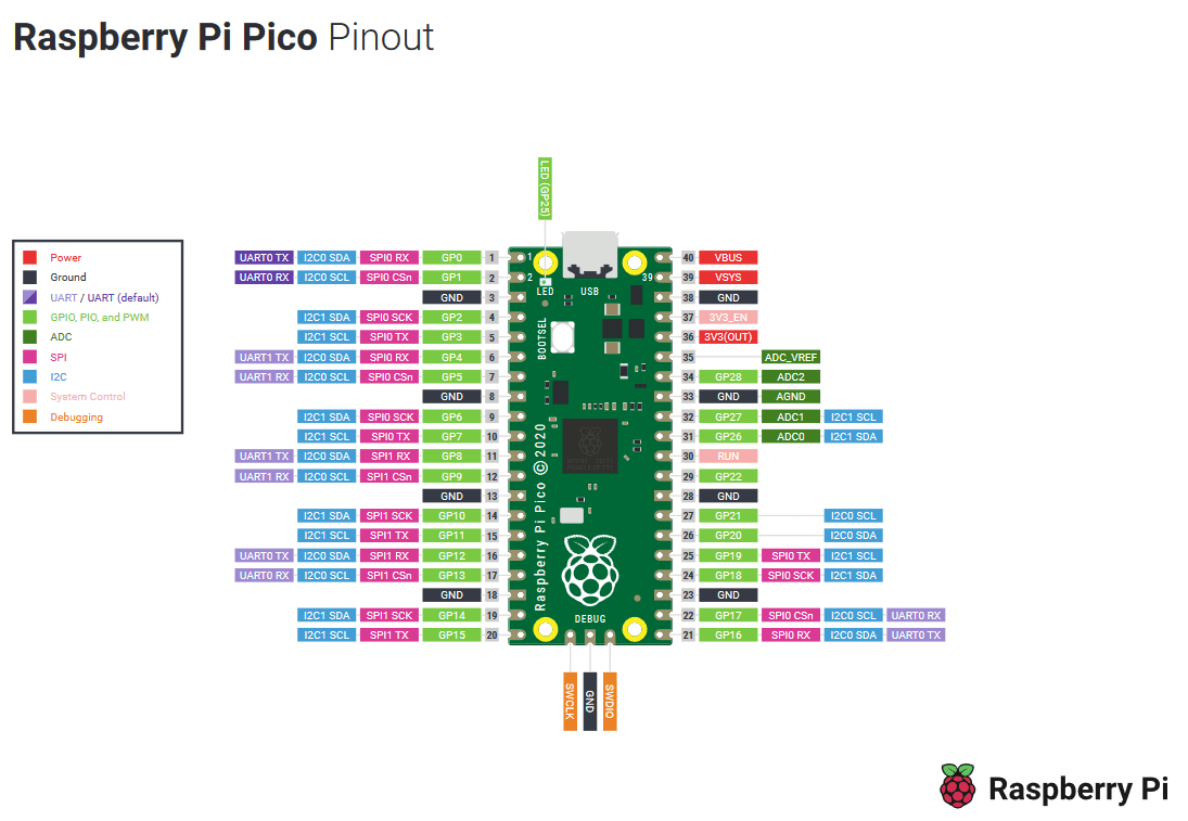
In this case, we specified gpio3, i.e. pin 5 (Pin numbers and GPIOs are usually different, see diagram below).
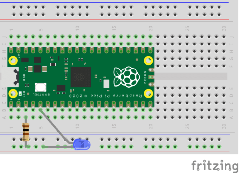
Wiring diagram
The external LED is connected via a 100 Ω resistor to connect pin 5 to pin 3 (GND).
Coding example
Using switches (input pins)
Description
Use InputPin to accept inputs such as switches.
In addition to OutputPin for LEDs, this should also be imported.
// GPIO traits
use embedded_hal::digital::v2::{OutputPin, InputPin};
This time, gpio5 is designated as the pin for the switch input.
// Set an input from a switch to gpio5
let switch = pins.gpio5.into_pull_up_input();
The input format used here is Pull Up. This is a method that the button is high when not pressed and low when pressed. Therefore,
// Blink the LED by a switch
loop {
    delay.delay_ms(5);
    if switch.is_high().ok().unwrap() {
        led_pin.set_low().ok().unwrap();
    } else {
        led_pin.set_high().ok().unwrap();
    }
}
means to create a circuit in which an LED lights up when a switch is pressed.
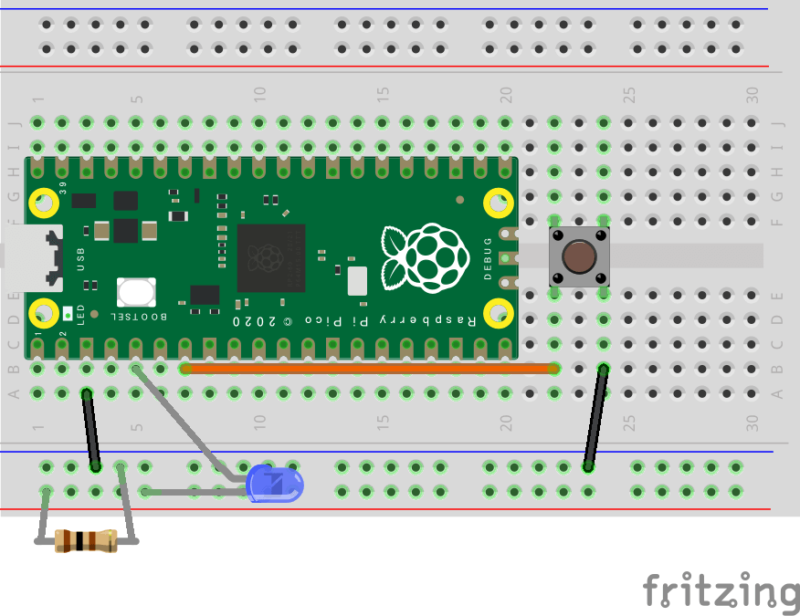
Wiring diagram
Coding example
Adjusting LED brightness (PWM basics)
Description
So far we have used embedded_hal::digital::v2::OutputPin to output signals from the Raspberry Pi Pico, but here we use the PWM function.
PWM is a method of representing continuous values with only a 0/1 output by varying the percentage of time the output is High.
This ratio of High time is called the Duty ratio.
use embedded_hal::PwmPin;(You can use gpio3 as in the previous two sections,) This time, use gpio5 as a PWM pin.
// Init PWMs
let mut pwm_slices = hal::pwm::Slices::new(pac.PWM, &mut pac.RESETS);

// Configure PWM2
let pwm = &mut pwm_slices.pwm2;
pwm.set_ph_correct();
pwm.enable();

// Output channel B on PWM2 to the LED pin
let channel = &mut pwm.channel_b;
channel.output_to(pins.gpio5);
The usage of the PWM is as follows.
- Create a PWM slice.
- Activating the PWM with the corresponding number (in this case
PWM2). - Defining channels and setting output pins (this time
channel_btogpio5)
There are two PWM channels, A and B, which can be used for two different signals.
Also, this time we specified PWM2 and channel_b because we are using gpio5, but these PWM numbers and channels change corresponding to the pin number.
The relationship between the PWM number/channel and the GPIO number is as follows.
| GPIO | 0 | 1 | 2 | 3 | 4 | 5 | 6 | 7 | 8 | 9 |
|---|---|---|---|---|---|---|---|---|---|---|
| PWM | 0A | 0B | 1A | 1B | 2A | 2B | 3A | 3B | 4A | 4B |
| GPIO | 10 | 11 | 12 | 13 | 14 | 15 | 16 | 17 | 18 | 19 |
|---|---|---|---|---|---|---|---|---|---|---|
| PWM | 5A | 5B | 6A | 6B | 7A | 7B | 0A | 0B | 1A | 1B |
| GPIO | 20 | 21 | 22 | 23 | 24 | 25 | 26 | 27 | 28 | 29 |
|---|---|---|---|---|---|---|---|---|---|---|
| PWM | 2A | 2B | 3A | 3B | 4A | 4B | 5A | 5B | 6A | 6B |
The key here is the brightness, which can be controlled by adjusting the duty ratio channel.set_duty().
let duty_max = channel.get_max_duty();
// Infinite loop, fading LED up and down
loop {
    delay.delay_ms(1000);
    channel.set_duty(duty_max);
    delay.delay_ms(1000);
    channel.set_duty(duty_max / 2);
    delay.delay_ms(1000);
    channel.set_duty(0);
}
The maximum value of the set_duty() argument can be obtained by get_max_duty().
The light is off when the duty ratio is 0 and brightest at the maximum value (equivalent to when 3.3 V is supplied from the normal OutputPin).
Note that the maximum value obtained by get_max_duty() is equal to the PWM parameter top described below.
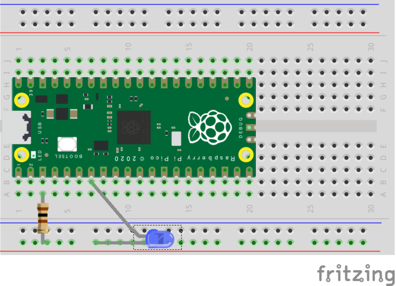
Wiring diagram
Coding example
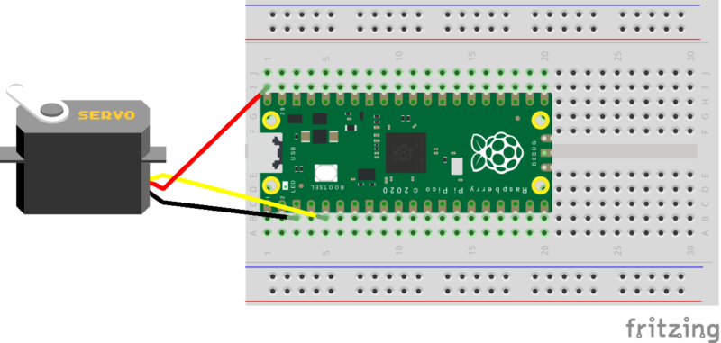
Controlling the servo (setting the PWM frequency)
Description
By using PWM, you can for example control servo motors in addition to adjusting LED brightness.
Here we will try to control the continuous rotation servo of the SG90-HV.
The basic frequency of the PWM is 125 MHz, the same as the clock frequency of the Raspberry Pi Pico, but this time we will control it down to 50 Hz.
// Set the PWM frequency to 50Hz
pwm.set_top(24999);
pwm.set_div_int(100);
pwm.set_div_frac(0);
The top and div variables can be used for frequency reduction.
Of these, div can be given as a fractional part, programmatically with set_div_int() and set_div_frac(), where the integer and fractional parts are given separately respectively.
If the number of clocks of the microcontroller is set to \(\mathrm{clk}\), the PWM frequency \(f\) is calculated as follows.
$$f=frac{mathrm{clk}}{(mathrm{top}+1)cdotmathrm{div}}$$
here,
$$mathrm{div}=mathrm{div{int}}+frac{mathrm{div{frac}}}{16}$$.
In this case,
$$f=frac{125times 10^{6}}{(24999+1)times 100}=50$$.
The servo speed can be controlled by the duty ratio.
// Infinite loop, rotating the servo left or right
// SG90-HV datasheet
// Right Max: 25000 *  5.0% = 1250
// Stop     : 25000 *  7.5% = 1875
// Left  Max: 25000 * 10.0% = 2500
loop {
    channel.set_duty(1250);
    delay.delay_ms(5000);
    channel.set_duty(1875);
    delay.delay_ms(5000);
    channel.set_duty(2500);
    delay.delay_ms(5000);
}
Wiring diagram
Coding example
Measuring time
Description
You can use the peripheral timer on the Raspberry Pi Pico to measure time.
// Create a timer
let timer = hal::timer::Timer::new(pac.TIMER, &mut pac.RESETS);
Let's implement a 1 Hz LED blinking without using delay.
// Blink the LED at 1 Hz
loop {
    led_pin.set_high().unwrap();
    let start = timer.get_counter().ticks();
    while timer.get_counter().ticks() - start < 500_000 {}
    led_pin.set_low().unwrap();
    let start = timer.get_counter().ticks();
    while timer.get_counter().ticks() - start < 500_000 {}
}
The Raspberry Pi Pico's peripheral timer advances the counter by one in 1 microsecond.
Therefore, you can implement a process equivalent to delay.delay_ms(500) by continuing to run the while statement until 0.5 seconds = 500,000 microseconds have passed, while checking the current counter value with timer.get_counter().ticks().
Note that if you write a program that does not use delay, it may compile without defining clocks, but this may result in a significant deviation in the accuracy of the timer.
Therefore, it is advisable to define clocks even if not used.
Wiring diagram
Coding example
Serial communication
Description
Serial communication allows you to output various information in the Raspberry Pi Pico to your PC.
To enable the terminal to be used for serial communication as well as writing files to the Raspberry Pi Pico, rewrite one line in .cargo/config as follows.
(In rp_pico_template, the following processing has already been done, so no changes are necessary)
# This runner will make a UF2 file and then copy it to a mounted RP2040 in USB
# Bootloader mode:
runner = "elf2uf2-rs -d -s" # after the change
# runner = "elf2uf2-rs -d" # before the change
The files in examples import what they need.
// USB Device support
use usb_device::{class_prelude::*, prelude::*};

// USB Communications Class Device support
use usbd_serial::SerialPort;
Within the main function, the USB bus, serial port and USB device are defined.
// Set the USB bus
let usb_bus = UsbBusAllocator::new(hal::usb::UsbBus::new(
    pac.USBCTRL_REGS,
    pac.USBCTRL_DPRAM,
    clocks.usb_clock,
    true,
    &mut pac.RESETS,
));

// Set the serial port
let mut serial = SerialPort::new(&usb_bus);

// Set a USB device
let mut usb_dev = UsbDeviceBuilder::new(&usb_bus, UsbVidPid(0x16c0, 0x27dd))
    .manufacturer("Fake company")
    .product("Serial port")
    .serial_number("TEST")
    .device_class(2)
    .build();
As an example, let's write a code to display hello! on the terminal every second.
let mut count = 0;
// Infinite loop, saying `hello!`
loop {
    delay.delay_ms(5);
    let _ = usb_dev.poll(&mut [&mut serial]);
    count += 1;
    if count == 200 {
        let _ = serial.write(b"hello!rn");
        count = 0;
    }
}
The display is done by serial.write(). Note that the string to be displayed must be a binary sequence.
Another point to note when performing serial communication is usb_dev.poll(&mut [&mut serial]).
This is a function that "asks" whether there is new data to be written or read via serial communication.
If this is not executed for a long time, serial communication will be terminated, so it is recommended to ask once every 5 milliseconds.
Therefore, the function outputs hello! after 200 5 milliseconds, which is a bit circuitous.
Coding example
Displaying numbers
Description
If you want to output a number, e.g. for serial communication, you need to convert this to a string type, which can be quite a difficult task in a no_std environment.
numtoa is a crate for this conversion.
// Convert a number to a string
use numtoa::NumToA;
The code to output hello! every second and at the same time display the cumulative number of times count_time can be written as follows.
let mut count = 0;
let mut count_time = 0;
// Buffer for NumToA
let mut buf = [0u8; 20];
// Infinite loop, saying `hello!` and counting the time
loop {
    delay.delay_ms(5);
    let _ = usb_dev.poll(&mut [&mut serial]);
    count += 1;
    if count == 200 {
        count_time += 1;
        let _ = serial.write(b"hello! x");
        let s = count_time.numtoa(10, &mut buf);
        let _ = serial.write(s);
        let _ = serial.write(b"rn");
        count = 0;
    }
}
When performing a conversion with NumtoA, a buffer buf = [0u8; 20] is required and should be defined beforehand.
You can then do .numtoa(10, &mut buf) on the integer type to convert it to a decimal string type.
This conversion is not supported for decimal types, so if you want to convert a certain decimal f: f64, for example, you need to follow these steps.
- Regarding
fas integer type (f_int = f as i32, cutting out integer part), convert it withnumtoaand display it. - Display
".". - Multiply
f - f_int as f64by a power of 10 according to the number of decimal places to be displayed, regard it as an integer type (rounding off the decimal part), convert it withnumtoaand display it.
(However, in step 3, it is necessary to fill in the zeros according to the number of digits.)
In order to simplify this labor, we have developed a crate called serial_write.
By using this crate,
- String
- integer
- Decimals
- Array of integers
- Array of decimals
can be displayed on a single line.
Decimals can also be displayed in exponential form.
Coding example
Applications.
Ultrasonic distance measurement (serial communication display)
Combine timer, PWM and serial communication to create a distance measuring device with ultrasonic sensor.

Comments